Major Milestone – Finished the Fuel Tanks – Is it Possible?

Got a bit of catching up to do here and I don’t have a lot of pictures so I’ll just get with it.

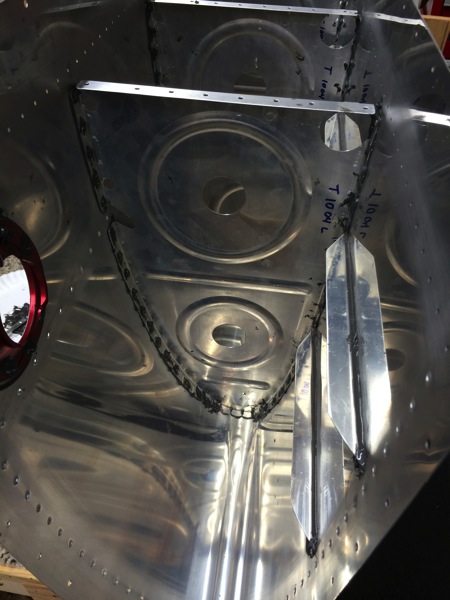
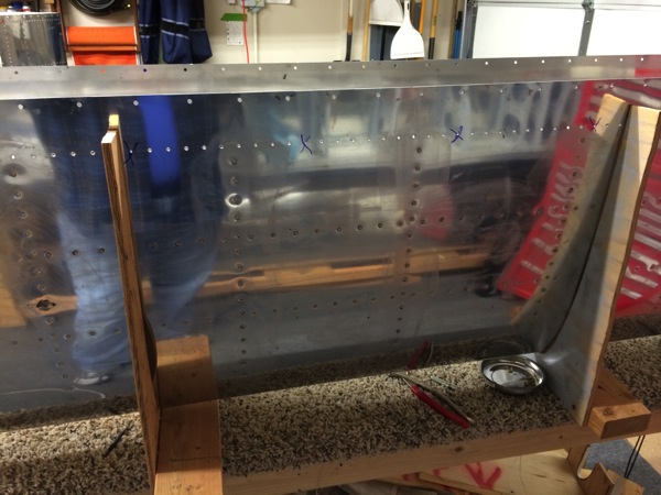
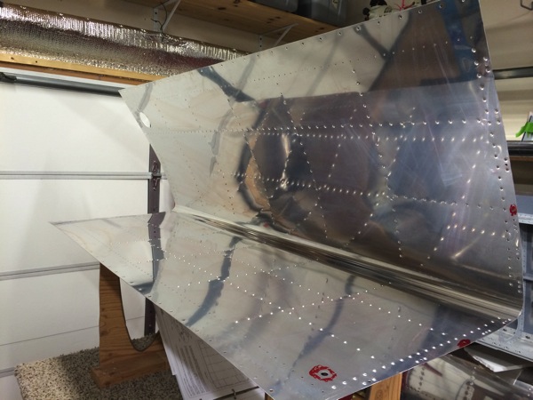
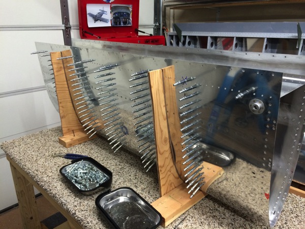
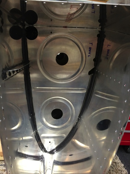
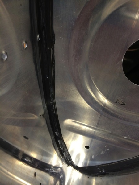
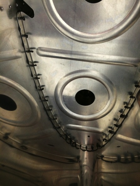
Since last update, I completed closing the right side tank by pro sealing and riveting the aft tank baffle. Right side went much like the left but I think I was a little more tidy with proseal along the skin to baffle rivet line so it didn’t squeeze out through all of the rivet holes nearly as bad.  Also, I only had time to do the Z-Bracket pop rivets so I let the skin-baffle rivets set up overnight under 100% clecos and riveted the next day.  That method is so much cleaner.

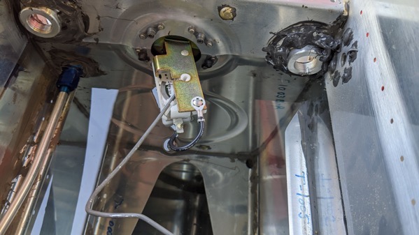
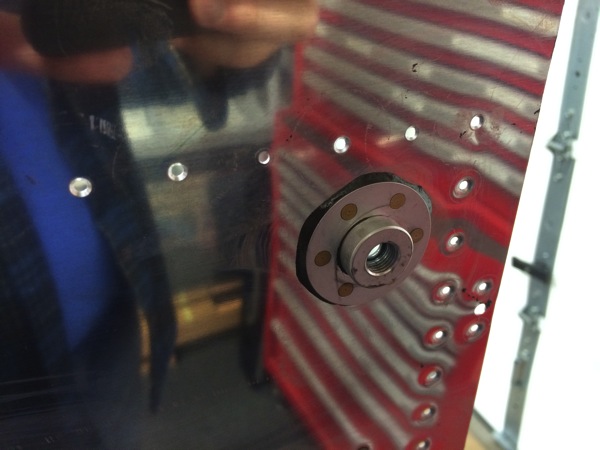
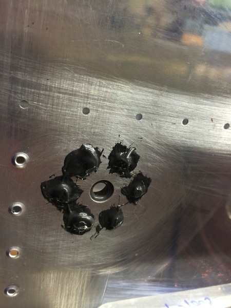
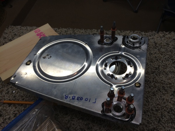
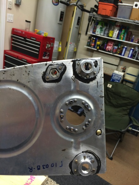
Now the final tasks for closing the tank are to proseal and install the fuel level sender and to install the various fittings for the fuel pick up, tank drain, etc.  I did the senders first.  That involves putting a thin smear of proseal on the tank’s mating surface then maneuvering the float wire and mechanism into the tank.  Then slowly tightening down the 5 cap head screws to evenly squeeze the proseal for what is essentially a “cured in place” gasket.

Last item to close the tanks and get them ready for leak testing is to install the fittings.  This can be counted as a lesson learned too late but it turned out ok in the end.  As I was preparing to install the tank drain fitting, I noticed that about 3/4 of the hole was blocked by proseal.  This would have been much easier to clear out from inside the tank before closing but it was too late for that.  So I ground down a razor blade so it was very narrow so it would fit into the drain hole. I then carefully carved away the proseal while being careful to extract the pieces so they wouldn’t become FOD in the tank.  It worked fine just took longer than it should have.

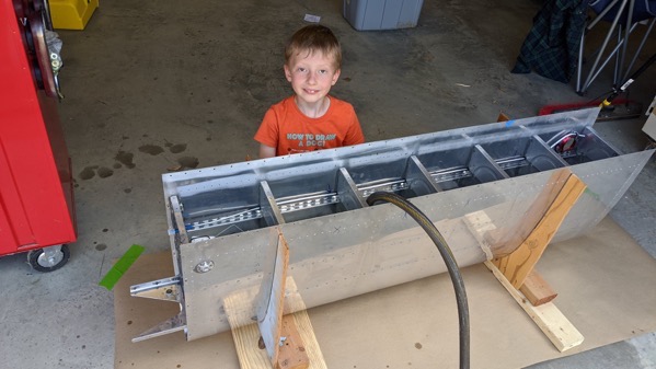
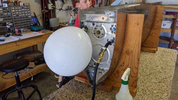
So finally, one of the days I’ve been apprehensive about since starting this build.  Yesterday was time to leak test the completed tanks.  The setup looks something like this, with a balloon on the fuel pickup fitting (secured with a zip tie) and a hose with a Schrader valve to allow for “pressurizing” the tank.  As long as the balloon is inflated, you know that there’s positive pressure in the tank so any leak should result in air coming out, and bubbles in soapy water.
IMG 20200606 140343 copy 

In an ideal world, the test fittings themselves wouldn’t leak so you could observe that the balloon doesn’t deflate.  Bun in my case, there was a leak around the balloon itself so I simply sprayed the entire tank with soapy water to look for bubbles.  I paid special attention to the troublesome areas such as the corners where three pieces of aluminum come together, the fuel sender, and everything having to do with the baffle.
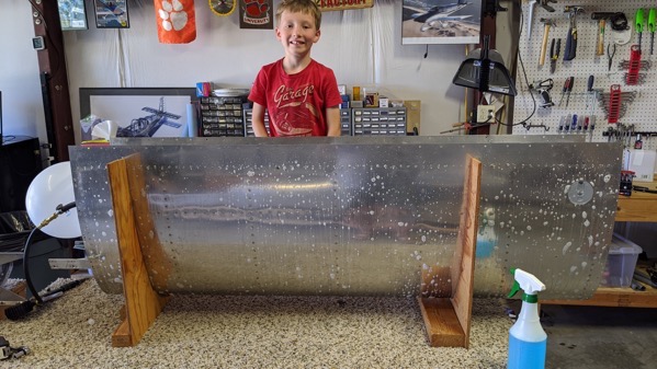
IMG 20200606 135952

In the end, the only leak I found was around the fuel cap on the right wing.  The fuel caps are adjustable so I can adjust it a little tighter but in reality, that’s at the tippy top of the tank so I really doubt it will be an issue even if I didn’t.
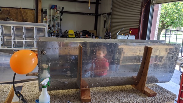
IMG 20200606 142327

I couldn’t be more excited to be past this milestone.  I will probably perform this test once more before hanging the tanks on the wing just to be sure but at least now I know they’re not leaking like a sieve.  

Fuel Tanks Almost Ready to Close

6 years ago I gave up on the step where you bend the fuel float wire to a shape that allows it to swing from top to bottom without hitting anything along the way.  I’ve dreaded the thought of coming back to that step and making it work even more than I’ve dreaded working with proseal.

I’m happy to report that I pulled the right tank off the shelf and pretty quickly got the float adjusted so that it stops about 1/8 inch above the bottom and 1/8 inch below the top.  Pretty good. This is why it’s a good idea sometimes to set something aside for a little while and come back.

IMG 20200522 170530

And a little video:

Well the next step in the plans is to install the tank “baffle” or the aft bulkhead. This will essentially close the fuel tanks so I decided to do a little interim leak test.

I took each tank and filled it with water up to the level of the remaining openings (sender unit and fuel pickup and return lines).  Happy to report that after filling and letting each sit a bit, no leaks from either tank.

IMG 20200523 155702

IMG 20200523 152623

Inboard Ribs, Proseal and Riveted

Last weekend I set up the inboard fuel tank ribs with proseal and 100% clecos.  I allowed them to set up over night and began riveting on Sunday.  I did roughly 1 rib a day for the rest of the week and today finished the last of the 5 inboard ribs.

IMG 20200508 165042 MP

So not done with proseal by any means but making progress towards that end.

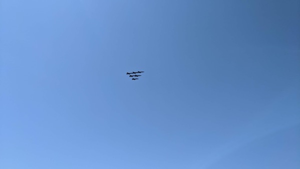
On Wednesday of this week, we took a little bit of time and went so see the Blue Angels fly over to recognize the healthcare workers during the Covid-19 crisis.

IMG 20200506 112115

Right Wing, First Rib

The proseal set up overnight and looks pretty good.  So I took an hour today while the boys were playing on the slip and slide to rivet the first rib.  I do like this process better than the wet proseal method.  Here’s the top of the wing skins with the first inboard rib riveted: 

IMG 20200503 180059

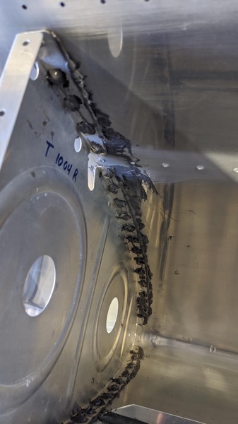
Here’s a view from the inside of the wing showIng the proseal added on top of the completed shop heads.

IMG 20200503 180127

That big glob of smeared proseal is a result of trying to clear out the channel for the J-stiffener which will be installed after the inboard ribs are completed.

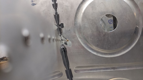
Here’s a view looking down the J-stiffener channel…

IMG 20200502 205842

Fuel Tanks 4

Last day that dad’s in town so I’d better get a full day’s work out of him…

We started by riveting the stiffeners, drain flange, and fuel filler flange on the right wing. Then we put the left side back in the cradle and set up to rivet the ribs. This is the time that fuel tank construction gets serious. For each rivet, the process goes something like:
1. Remove Cleco
2. Clean out hole of excess sealant from the overnight set up
3. Apply small dab of sealant to the dimple
4. Insert rivet. It will sit in this bed of fresh sealant.
5. One person holds the bucking bar, the other drives the rivet.
6. Repeat about 30 times for each of the 5 inboard ribs.
7. Use a small brush and apply a dab of sealant to the newly formed shop head of each rivet.

Short version of the story is that we worked all day and finished the inboard ribs.

One of the inboard ribs
IMG 3100

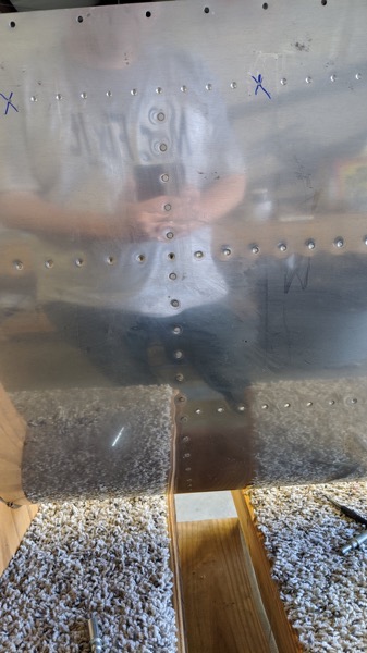
Bottom of the fuel tank. You can see the vertical rows of rivets for the ribs and the horizontal rows for the stiffeners
IMG 3101

Fuel tank drain flange
IMG 3102

Inside of the fuel tank drain. You get a good look at the sealant applied to the rivet shop head.
IMG 3103

I’m very pleased with the progress we made over the past week. We worked nearly 30 hours (58 man hours) and made significant progress on the fuel tanks. Thanks for the help Dad!

Fuel Tanks 1

First of all, Vans changed the numbering of the sections so I’ll just stop using section numbers in the titles to avoid confusion.

We have started on the tanks. I have been putting it off for a while because I was intimidated by the pro-seal. After reading quite a bit online from builders logs and forums on =VAF=, I decided to go with the method described by Rick Galati in this thread.

Speaking of other builders sites, I want to point anyone to Jim Novak’s RV-8 build log. Dad and I visited Jim’s shop yesterday and I spent most of yesterday evening catching up with his build log. I’ve gotten behind on several things since G was born and Jim’s log is one of them but he does a very good and thorough job of documenting his work. I read his section on tanks twice last night and this morning before we started sealing the ribs. Rather than go through the details of the process here, read Rick’s thread above and start here on Jim’s log and read from there.

Freshly dimpled and prepared skin ready for ribs, sealant, and rivets…
IMG 3085

First sealing step is to proseal the fuel line fittings to the inboard rib. We applied a healthy (if not pretty) layer of pro seal to the mating surfaces then clecoed every hole. We’ll leave this set up over night and rivet it the next morning.
IMG 3083

and here is the completely riveted piece.
IMG 3092

Next step is to seal then rivet the tank stiffeners onto the lower portion of the skin. Since I neglected to take any pictures of this you’ll have to use your imagination but we layer a bead of sealant then 100% clecoed the stiffeners. They set up over night and we riveted them this morning.

Next we installed the inboard ribs in the tank skin. We did this by applying pro seal to the raying surface (mating surface) of the rib then 100% clecoed them into place starting at the nose and working our way back.
IMG 3087

After that, we used the pro seal that squeezed out plus some additional pro seal to make a fillet on the non flanged side of the rib. We’ll do more on the flange side after riveting but it seemed like it would just make a mess to do it now. You can see the fillet here.
IMG 3088
and here
IMG 3089

This is what the flange side of the ribs look like. You can see that pro seal has squeezed out from the raying surface but we’ll add another layer after the rivets go in. Better safe than sorry….
IMG 3090

We’re going to work on the right side tomorrow and probably rivet the left side Thursday.